Phone:
(701)814-6992
Physical address:
6296 Donnelly Plaza
Ratkeville, Bahamas.

Phone:
(701)814-6992
Physical address:
6296 Donnelly Plaza
Ratkeville, Bahamas.

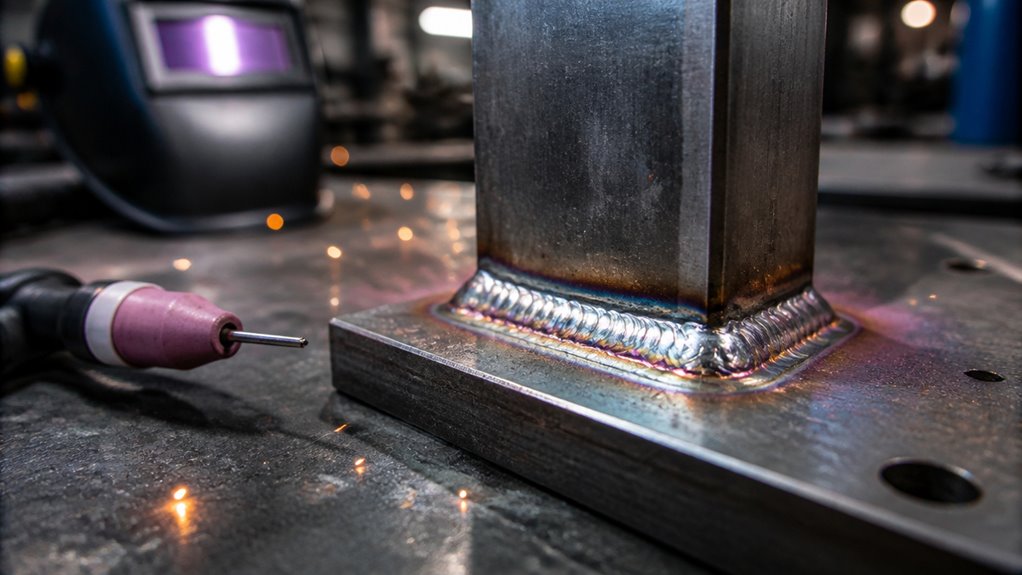
A weld symbol is a standardized graphic on engineering drawings that tells you exactly how and where to weld a joint, eliminating guesswork.
It uses a reference line and arrow to pinpoint weld location, with symbols indicating weld type like fillet or groove. Additional notes in a tail provide process details.
These symbols help guarantee consistent fabrication, quality control, and communication across teams. Understanding these symbols is key to mastering welding requirements and quality standards.
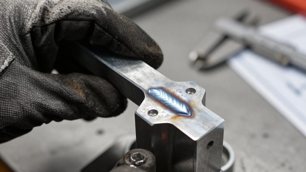
Although weld symbols may seem like simple markings on a drawing, they play a critical role in conveying precise welding requirements to everyone involved in fabrication and inspection.
You rely on weld symbols as standardized graphic characters that specify joint geometry or weld types clearly and efficiently.
They serve as shorthand to communicate weld size, type, and related processing details without ambiguity.
By using these symbols, you guarantee consistent interpretation across design, fabrication, and quality control teams, minimizing errors.
Welding symbols follow established standards like AWS A2.4, which define their construction and meaning, so you can trust the instructions conveyed.
Understanding weld symbols allows you to coordinate welding execution accurately, improving workflow and reducing costly miscommunication on complex projects.
Using the reference line as a central anchor helps organize all welding information clearly on drawings.
A welding symbol consists of several fundamental components that work together to convey detailed welding instructions.
First, the horizontal reference line acts as the central axis, anchoring the entire symbol.
The arrow, connected to this line, points directly to the joint requiring welding, defining the weld location precisely.
The arrow links the reference line to the joint, pinpointing the exact weld location with precision.
You’ll find the weld symbol itself positioned on or near the reference line, indicating the specific weld type needed.
The tail, attached to the opposite end of the reference line, provides space for additional details such as welding process notes, specifications, or procedure references.
Supplementary symbols and dimensions may also appear, clarifying weld size, contour, finish, or other critical requirements.
Understanding these core parts guarantees accurate interpretation and execution of welding tasks.
For critical structural joints, understanding symbols related to complete joint penetration (CJP) welds is essential to ensure full strength and integrity.
You’ll often come across fillet and groove weld symbols. They’re pretty essential because they define basic joint types and their geometry.
Then there are spot and seam weld symbols, which are used for localized or continuous welds. These are especially important when working with sheet metal and thin components.
Getting a good grasp of these symbols really helps ensure clear communication of weld requirements during fabrication and inspection processes. It’s all about making sure everyone is on the same page!
Understanding the differences between fillet and groove welds is crucial for selecting the appropriate symbol and welding technique.
Fillet and groove weld symbols form the foundation of weld communication, representing the most commonly specified joint types in fabrication.
When you read a fillet symbol, a right triangle on the reference line, you’ll know it indicates a weld joining two surfaces at approximately a 90-degree angle. This is typically seen on T-joints or lap joints.
Groove weld symbols, however, describe welds made within a prepared groove between parts, such as V, U, or J grooves. These symbols specify groove shape, size, and root opening, which are critical for achieving proper penetration and strength.
You’ll find groove weld symbols placed either above or below the reference line, indicating the weld side. Understanding these symbols allows you to interpret joint preparation and welding requirements accurately. This ensures consistent fabrication quality and structural integrity. Proper groove geometry and joint preparation are essential for complete joint penetration, which directly impacts weld strength and durability.
Spot and seam weld symbols convey critical information about weld type and placement, enabling precise communication for surface joining processes.
Spot weld symbols typically feature a circle on the reference line, indicating a weld at discrete points where sheets or components join.
Seam weld symbols resemble a continuous line, representing a uniform weld along a joint, often used for overlapping metal sheets.
You’ll find dimensions like weld diameter for spot welds and pitch or length for seam welds explicitly noted beside the symbols.
Their placement above or below the reference line specifies the joint side requiring welding.
Understanding these symbols helps you accurately interpret fabrication requirements.
This ensures consistent weld quality and proper structural performance in sheet metal assemblies and other applications requiring surface joining.
Spot welds are ideal for joining thin sheet metals, typically between 0.5 and 3 millimeters thick, by generating heat through electrical resistance.
To read weld symbols accurately, you’ll want to start by looking at the reference line. This line is the anchor for all the welding instructions, so it’s kind of the starting point.
Next up, you should check out the arrow and the tail. The arrow points directly to the joint side that needs attention, while the tail is where you’ll find any process notes or specifications. It’s like getting the extra details you need for the job.
Lastly, pay attention to where the weld symbol is placed in relation to the reference line. This placement tells you which side of the joint requires welding. It’s all about piecing the information together to get a clear picture of what you need to do! Following a Welding Procedure Specification ensures that the weld is performed consistently and meets quality standards.
When you examine weld symbols on engineering drawings, the reference line serves as the fundamental element anchoring all related information.
This horizontal line acts as the baseline where weld symbols, supplementary symbols, and dimensions are positioned.
You’ll notice weld symbols placed either above or below this line, indicating the side of the joint to be welded.
Above indicates the other side, while below indicates the arrow side.
The reference line connects all instructions, ensuring you interpret weld type, size, length, and contour consistently.
Its central role allows you to distinguish between weld specifications and procedural notes, typically found in the tail area.
These notes don’t interfere with the reference line’s clarity.
Mastering reference line basics is essential for precise and unambiguous weld communication.
Understanding the groove design indicated by weld symbols is crucial for achieving full penetration and strong butt welds.
Although the reference line anchors the weld symbol, the arrow and tail provide critical context that directs your interpretation. The arrow points precisely to the joint location requiring welding, distinguishing the arrow side for weld placement.
This directional cue guarantees you correctly identify which side of the joint the weld applies to, critical for accurate fabrication. The tail, when present, holds supplementary information such as welding processes, specifications, or reference codes.
You’ll find process notes here that clarify particular welding methods or procedural details not conveyed by the symbol alone. Together, the arrow and tail integrate with the reference line and weld symbol to form a complete directive.
Understanding their roles enables you to read weld symbols accurately, guaranteeing precise communication and execution on engineering drawings. Additionally, following the Welding Procedure Specification (WPS) ensures the welding process complies with essential parameters and quality standards.
Since weld symbol placement directly impacts how you interpret welding requirements, understanding their exact location on engineering drawings is essential. The weld symbol’s position relative to the reference line tells you which side of the joint needs welding.
If the symbol is below the line, it applies to the arrow side; above, it indicates the other side. You must analyze the arrow direction, reference line, and any tail notes together for accurate interpretation.
Key points to contemplate include:
Correct placement guarantees precise communication of weld instructions. Mastery of multiple welding positions is essential for accurately executing the instructions conveyed by these symbols in various joint configurations, especially in challenging orientations like pipe positions.
Understanding weld symbol placement is essential because it directly indicates which side of the joint requires welding.
When you see a weld symbol on a drawing, its position relative to the reference line tells you whether to weld on the arrow side or the other side of the joint.
If the weld symbol sits below the reference line, you weld on the arrow side; if it’s above, you weld on the opposite side.
The arrow itself points to the joint location, serving as a directional guide.
This placement eliminates ambiguity, ensuring you apply the weld precisely where intended.
Proper weld application also depends on mastering weld pool control to achieve strong, defect-free joints in various welding positions.
When you examine a weld symbol closely, you’ll find it conveys critical details such as weld size, length, and finish requirements that directly impact fabrication quality.
These elements assure the weld meets strength, appearance, and functional criteria essential for the joint’s performance. Understanding these details lets you interpret the design intent accurately and execute the weld accordingly.
Ensuring welds meet strength and appearance standards is key to fulfilling the design intent and joint function.
Key details weld symbols communicate include:
These specifications guide precise fabrication and inspection processes.
Although weld symbols may seem straightforward, interpreting them correctly requires familiarity with established standards like those from AWS and ANSI. These standards guarantee uniformity in welding communication, reducing errors and enhancing clarity.
AWS A2.4 defines how to specify welding and inspection information precisely, while ANSI complements with additional symbol conventions.
| Standard | Focus Area | Key Feature |
|---|---|---|
| AWS A2.4 | Welding and NDE symbols | Comprehensive symbol system |
| ANSI | General engineering symbols | Supplemental symbol details |
| AWS A2.4 | Symbol construction | Reference line & arrow rules |
| ANSI | Symbol placement | Above/below line distinctions |
| AWS A2.4 | Specification notes | Tail for process instructions |
You’ll rely on these standards to read weld type, location, size, and inspection info accurately. This guarantees consistent fabrication and communication.
Because weld symbols provide clear, standardized instructions, they markedly enhance both fabrication accuracy and quality control.
Weld symbols deliver precise, standardized guidance that significantly improves fabrication accuracy and quality control.
When you use weld symbols, you eliminate ambiguity about weld type, size, and location, which guarantees consistent execution. This clarity supports seamless communication between designers, welders, and inspectors, reducing errors and rework.
You’ll find that weld symbols also facilitate precise quality control by specifying inspection requirements and acceptance criteria directly on drawings.
Key benefits include:
Employing weld symbols allows you to optimize production workflows and maintain rigorous quality assurance standards.
You create weld symbols by following standardized guidelines like AWS A2.4, which detail the reference line, arrow, tail, and specific weld characters.
Engineers or welding specialists design them based on joint requirements and fabrication needs. They carefully select symbols to convey precise weld types, sizes, and processes.
This ensures consistent communication across design, fabrication, and inspection teams. You must interpret these symbols accurately to execute or verify welds correctly.
Of course, you can just scribble any symbol you fancy and hope for the best.
Said no professional ever. Weld symbols must adhere to strict standards like AWS A2.4 to guarantee clarity and safety.
While you can add project-specific notes in the tail or supplementary symbols, you can’t arbitrarily customize core symbols without risking misinterpretation.
Precision and standardization trump creativity here. Your weld symbols need to communicate unambiguously across teams and inspections.
You need formal training in welding blueprint reading, often provided through AWS-certified courses or technical institutions, to interpret weld symbols properly.
This training covers AWS A2.4 standards, symbol components, and their meanings. You’ll learn to analyze reference lines, arrows, weld symbols, and supplementary details precisely.
Hands-on practice with real drawings guarantees you accurately understand weld size, type, location, and process notes. This minimizes errors in fabrication and inspection.
You’ll find that weld symbols differ internationally mainly due to varying standards like AWS in the U.S. and ISO globally.
These standards affect symbol shapes, placement, and supplementary details.
While AWS A2.4 uses a reference line and arrow system, ISO symbols might include different conventions for weld size or finish.
You must understand the applicable standard to interpret symbols accurately, ensuring your weld meets the required specs across regions.
Imagine weld symbols as the silent language guiding robotic arms.
Yes, automated welding systems use weld symbols extensively to program precise welding parameters.
You rely on these standardized symbols to convey joint details, weld type, size, and location, ensuring consistent execution without human error.
By translating these symbols into machine instructions, automated systems achieve accuracy and repeatability.
This streamlines fabrication and quality control in complex manufacturing environments.
When you recognize weld symbols, you not only decode detailed instructions but also anticipate quality and precision in fabrication. This bridges design intent with real-world execution.
Understanding their placement, size, and standards guarantees you avoid costly errors and miscommunication.
So, mastering weld symbols isn’t just about reading drawings; it’s about controlling outcomes, improving quality, and streamlining production.
This proves that what seems like a simple mark holds critical technical significance in your engineering workflow.