Phone:
(701)814-6992
Physical address:
6296 Donnelly Plaza
Ratkeville, Bahamas.

Phone:
(701)814-6992
Physical address:
6296 Donnelly Plaza
Ratkeville, Bahamas.

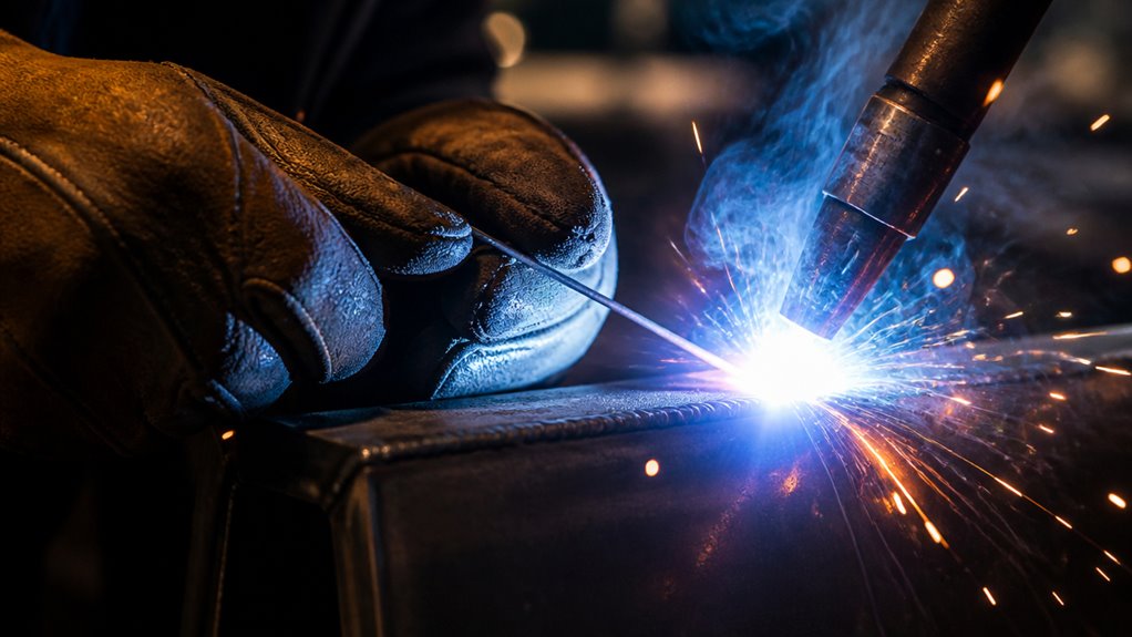
To weld wire, feed a continuous electrode through the gun while maintaining a steady arc length around 1/4 inch.
Trigger the welder to ignite the arc and deposit filler metal, adjusting wire feed speed to match your material and avoid burnback or spatter.
Position the torch at the proper angle, typically 20–30°, and move at a consistent pace for clean penetration and bead shape.
Keep surfaces clean and guarantee proper gas flow to prevent defects.
Master these basics to enhance your welding technique and efficiency.
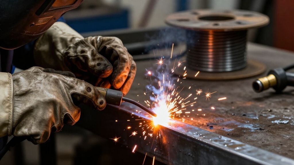
Wire welding relies on feeding a continuous wire electrode through a welding gun while maintaining an electric arc between the wire and the workpiece.
When you press the trigger, the arc ignites, and the wire feed starts automatically. The molten wire acts as filler metal, joining the base materials.
Pressing the trigger starts the arc and wire feed, melting filler metal to join materials seamlessly.
To protect the weld pool from contamination, you typically use shielding gas directed around the wire at the nozzle.
The wire, supplied from a reel, passes through a contact tip that conducts current and guides the wire into the weld zone.
You must keep the wire feed steady and maintain a proper arc length to guarantee consistent penetration and bead formation.
This semi-automatic process allows precise control over weld quality and efficiency.
Proper wire feed speed adjustment is essential to avoid defects such as poor penetration or spatter.
Understanding how the welding gun feeds the electrode and maintains the arc sets the stage for choosing the appropriate wire welding method.
You need to take into account the base material, joint design, and environmental conditions before selecting between Gas Metal Arc Welding (GMAW) or Flux Cored Arc Welding (FCAW).
Use GMAW with solid wire and shielding gas for clean, thin metals requiring minimal spatter.
Opt for FCAW when working outdoors or on dirty surfaces, as flux-cored wire provides inherent shielding and better penetration.
Also, factor in the wire diameter and compatibility with your machine’s polarity.
Selecting the right method guarantees efficient wire feed, stable arc, and strong welds.
Avoid mismatch to prevent defects like burnback or poor fusion, which compromise joint integrity.
Additionally, choosing the correct shielding gas is crucial to optimize weld quality and minimize spatter.
First things first, you want to set up your power source. Check the wire manufacturer’s polarity specs to ensure you have peak arc stability. It’s really important to get this right!
Next, let’s talk about the wire feed speed. You’ll want to adjust it carefully based on the type of electrode you’re using. This helps you steer clear of issues like burnback or poor penetration. Nobody wants that!
Oh, and don’t forget about your welding gun cable. Keeping it straight and limiting the wire extension to about half an inch can really help you achieve consistent feed and a steady arc. Trust me, it makes a difference!
Also, maintaining the proper stickout length—about 3/8 inch—ensures stable arc and consistent weld quality throughout your work.
Before powering up your welding machine, make sure the power source matches the wire electrode’s polarity requirements exactly.
Check the wire manufacturer’s specifications for recommended polarity. Most solid wires require direct current electrode positive (DCEP), while some flux-cored wires need direct current electrode negative (DCEN).
Connect the welding leads accordingly to avoid arc instability or poor weld quality. Confirm the machine’s input voltage and amperage are suitable for your wire type and thickness.
Make certain all electrical connections are secure and insulated to prevent shorts or shocks. Verify your machine’s mode (constant voltage for MIG welding) is correctly set.
Finally, inspect the ground clamp placement on a clean metal surface to maintain a stable circuit. Proper power source configuration guarantees consistent arc performance and weld integrity.
Always confirm electrode lead connections match the correct polarity to optimize heat distribution and metal transfer.
Adjust the wire feed speed carefully to match the specifications of your wire electrode and the welding application.
Set the speed too low, and you risk poor penetration, inadequate joint fill, or wire burnback at the contact tip.
Too high, and you’ll cause excessive spatter and unstable arc conditions. Consult the wire manufacturer’s chart for initial speed settings based on wire diameter and material thickness.
Use the machine’s controls to fine-tune the feed until you achieve a consistent, stable arc and smooth bead formation. Keep the welding gun cable straight to prevent erratic wire feeding.
Make certain the wire extends no more than 1/2 inch beyond the nozzle to maintain peak arc length and shielding gas coverage. Test on scrap material before final welding.
Regularly calibrate your wire feed speed by measuring the wire output over six seconds to ensure accurate feed speed calibration.
When preparing joints and workpieces for welding, you must make sure the surfaces are thoroughly clean to promote strong fusion.
Remove all rust, paint, oil, and dirt using a wire brush or grinder to expose bare metal.
Inspect joint edges and bevel them slightly if necessary, depending on the joint type, to guarantee proper penetration.
Fit parts tightly with minimal gaps and use tack welds to secure alignment before welding.
Maintain correct joint angles, typically 90° for butt joints and about 45° for fillet welds, to optimize bead shape and penetration.
Keep the workpieces stable on a flat surface to prevent shifting.
Performing practice welds on scrap material of the same thickness helps verify fit-up and joint readiness before proceeding with the final weld.
Ensure metal is dry and free of contaminants by visually and tactilely inspecting surfaces to avoid contamination and porosity.
After securing the workpieces and confirming proper joint fit-up, focus shifts to setting the wire feed speed and voltage on the welding machine.
Begin by consulting the wire manufacturer’s specifications for recommended settings based on wire diameter and material.
Start by reviewing the wire manufacturer’s guidelines for settings according to wire size and type.
Adjust the wire feed speed to regulate the filler metal deposition rate. Too slow causes poor penetration and burnback, while too fast leads to excessive spatter.
Next, set the voltage to control arc stability and bead shape. Higher voltage increases arc length and bead width, while lower voltage tightens the arc.
Use incremental adjustments, testing on scrap material to achieve a smooth, consistent arc with stable wire feeding.
Make certain the wire extends about 1/2 inch from the nozzle without excessive protrusion.
Proper feed speed and voltage settings optimize weld quality and minimize defects.
Listen carefully to the arc’s steady crackling sound as an indicator of ideal settings to help fine-tune your weld parameters.
To get the best results when welding, it’s really important to position the welding gun at the right angle. This helps ensure you achieve proper penetration and a good bead shape. So, depending on the type of joint you’re working with, you’ll want to adjust the torch angle. For butt joints, aim for around 90°, while for fillet welds, a 45° angle works best.
Now, here’s a tip: keeping your welding gun in a consistent position is key. It really helps you control the weld pool, which in turn prevents any defects from popping up. Just remember, practice makes perfect! Additionally, ensuring a stable electrical connection between the contact tip and wire is essential for maintaining arc stability during welding.
Although proper torch angle varies with the joint type, maintaining the correct positioning of the welding gun is critical for achieving consistent penetration and bead shape.
You should hold the torch at an angle that directs the arc force into the weld pool to control penetration and minimize spatter.
Too steep or too flat an angle can cause poor fusion or excessive weld buildup. Adjust angles based on joint geometry but aim for a smooth, controlled arc.
Regular practice and maintaining a steady hand are essential to mastering the proper torch angle and producing clean, high-quality welds.
| Torch Angle (Degrees) | Effect on Weld Quality |
|---|---|
| 10-15 | Minimal penetration, spatter |
| 20-30 | Optimal penetration, clean bead |
| 40-50 | Wider bead, less penetration |
| 60+ | Poor fusion, unstable arc |
| 90 | Edge joint penetration focus |
Use this as your baseline for torch angle adjustments.
Mastering gun positioning techniques builds directly on maintaining ideal torch angles to guarantee consistent weld quality. You’ll want to hold the welding gun steady and maintain the correct angle relative to the workpiece.
Proper positioning secures peak wire feed and arc stability. Focus on these key points:
Regularly cleaning and maintaining contact tips and nozzles also helps ensure consistent wire feeding and stable arc performance.
When welding different joint types, adjusting the gun and torch angles is essential to guarantee proper penetration and bead formation.
For butt joints, hold the gun perpendicular at about 90°, ensuring the arc is centered along the joint line.
For fillet welds, tilt the torch approximately 45° toward the weld to effectively fill the corner and achieve proper fusion.
When working with lap joints, angle the gun to direct the arc slightly toward the top plate to avoid lack of fusion.
Maintain a consistent drag angle of 10° to 15° in the direction of travel to control the weld pool and bead shape.
Always adapt your positioning based on joint geometry to optimize arc stability and minimize defects.
Control your welding bead by choosing between stringer and weave techniques, each suited for different joint requirements and weld widths.
Stringer beads use a steady, straight-line motion, ideal for narrow joints and deeper penetration. Weave beads employ a side-to-side motion, creating a wider bead for filling larger gaps or covering uneven surfaces.
Consider these points when selecting your technique:
Mastering these techniques improves weld strength and appearance while matching joint demands.
You really need to focus on the weld puddle instead of just staring at the arc. Trust me, it makes a big difference in controlling bead shape and penetration.
Keeping a consistent arc length is key too; it helps maintain stable heat input and prevents issues like undercut or burn-through.
When you watch the puddle, you can actually make real-time adjustments to your travel speed and torch angle. This way, you’re set up for peak weld quality every time.
It’s all about that connection with what you’re doing!
Focusing on the weld puddle lets you directly monitor the molten metal’s behavior. This ensures consistent bead formation and penetration.
By watching the puddle, you can adjust your technique in real time to avoid defects like undercut or lack of fusion.
Here’s what to focus on:
Although maintaining a consistent arc length may seem challenging at first, it’s essential for producing a smooth, uniform weld bead.
You should keep the distance between the wire tip and the workpiece steady, typically around 1/8 to 1/4 inch, depending on wire diameter and current settings.
Too long an arc causes excessive spatter and a wide, uneven bead.
Too short an arc risks sticking the wire and burnback.
Focus on the weld puddle, not the bright arc, to gauge arc length accurately.
Adjust your hand steadily and avoid sudden movements.
Using the correct wire feed speed and voltage settings also supports maintaining arc length.
Consistency here directly controls bead shape, penetration, and overall weld quality.
Practice will help you develop the precise control needed.
Since wire welding generates intense light, heat, and fumes, wearing the proper safety gear is essential to protect your eyes, skin, and respiratory system. Neglecting these precautions can lead to severe injuries or long-term health issues.
Focus on these three critical items:
Always inspect your gear before starting to confirm maximum safety.
Frequently, wire welding can present issues that disrupt the quality and efficiency of your welds. You might face problems like burnback, porosity, or poor penetration. Identifying and correcting these quickly guarantees strong, clean welds.
Check wire feed speed, voltage settings, and torch angle first. Clean your workpiece thoroughly to avoid contamination. Maintain a steady arc length and consistent travel speed.
| Problem | Cause | Solution |
|---|---|---|
| Burnback | Low wire feed speed | Increase wire feed speed |
| Porosity | Contaminated surface/gas | Clean surface, check gas flow |
| Poor Penetration | Low voltage or incorrect angle | Adjust voltage, correct torch angle |
You need to regularly clean the contact tip and nozzle to prevent spatter buildup, guaranteeing consistent wire feed and arc stability.
Check the wire feed mechanism for wear and replace worn rollers or liners.
Inspect cables and connections for damage or looseness to avoid erratic arc behavior.
Keep the wire reel properly seated and guarantee the drive tension is correct.
Finally, verify that shielding gas flow is steady and leak-free for peak weld quality.
You should know that up to 70% of weld defects link directly to poor environmental control.
Moisture or wind can cause porosity by contaminating the shielding gas, weakening your weld.
Cold temperatures make the weld pool solidify too quickly, risking cracks.
Dust and debris reduce arc stability, leading to irregular beads.
Always weld in a clean, sheltered space with controlled humidity to guarantee consistent, high-quality wire welds.
Yes, you can automate wire welding for large-scale production.
Automated systems feed wire continuously, control arc parameters precisely, and maintain consistent shielding gas flow. You’ll program the robot or machine to follow specific joint paths with repeatable torch angles and speeds.
This boosts productivity, weld quality, and reduces human error. Make certain your equipment matches wire type and material specifications to optimize automation performance and maintain strict quality control.
You’ll find FCAW wire costs about 15-25% more than MIG wire. However, FCAW often reduces overall expenses by cutting gas use since its flux core provides shielding.
MIG requires continuous shielding gas, raising operational costs. However, MIG equipment is generally less expensive and easier to maintain.
If you prioritize lower initial machine investment, MIG is better. But FCAW saves you money on consumables and works well outdoors or with thicker materials.
Different metals demand specific wire electrodes to ensure proper fusion and strength.
You’ll choose solid wire for clean steels, while flux-cored wire suits thicker or dirty metals.
For aluminum, use aluminum-specific wires with inert gas shielding.
Stainless steel requires matching stainless electrodes to avoid contamination.
Always match the electrode composition to the base metal to prevent cracking, guarantee corrosion resistance, and achieve peak weld quality and mechanical properties.
Now that you’ve mastered the basics of wire welding, it’s ironic how something that looks like molten chaos actually demands such precise control and technique.
You’ll find that setting the right wire feed speed, voltage, and bead pattern isn’t guesswork; it’s science.
So, don’t underestimate the power of preparation and safety gear; they’re your best allies in turning sparks into strong, clean welds.
Welding’s complexity may surprise you, but that’s what makes it rewarding.