Phone:
(701)814-6992
Physical address:
6296 Donnelly Plaza
Ratkeville, Bahamas.
Phone:
(701)814-6992
Physical address:
6296 Donnelly Plaza
Ratkeville, Bahamas.
A welding transformer works by stepping down high-voltage, low-current AC into low-voltage, high-current AC suitable for welding.
You supply voltage to the primary winding, which has many turns of thin wire, inducing a current in the secondary winding with fewer turns and thicker wire to handle up to 1000 amperes.
You control output by adjusting taps or a magnetic shunt to maintain stable arc conditions.
Understanding these details reveals how transformers guarantee reliable welding performance.
When you power up a welding transformer, it steps down high-voltage, low-current alternating current (AC) from the supply line into low-voltage, high-current AC suitable for welding.
A welding transformer converts high-voltage, low-current AC into low-voltage, high-current AC ideal for welding.
It operates on electromagnetic induction, where the primary winding receives the supply voltage, inducing a voltage in the secondary winding.
The transformer reduces input voltage from typical levels of 208 to 600 volts down to a range between 20 and 100 volts.
Simultaneously, it increases current output up to 1000 amperes or more, which is essential for creating and sustaining a welding arc.
This voltage-current transformation is governed by the turns ratio between the primary and secondary coils, ensuring power balance while delivering the high current density necessary for effective arc generation and metal fusion.
Welding transformers supply AC by stepping down voltage and increasing amperage, which is fundamental to meeting the high current demands of welding processes and enabling effective arc welding.
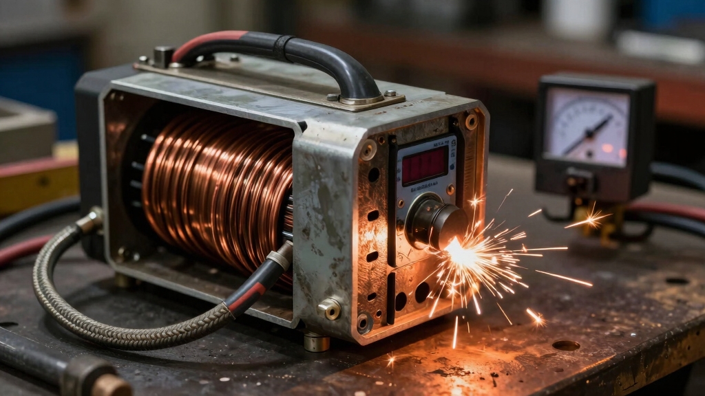
Although welding transformers vary in design, their core components consistently perform critical functions to convert and control electrical energy for welding.
You’ll find a magnetic core, primary and secondary windings, and a magnetic shunt working together to regulate current and maintain efficient coupling.
| Component | Description | Function |
|---|---|---|
| Magnetic Core | Iron core | Channels magnetic flux for induction |
| Primary Winding | Many turns of smaller wire | Receives input voltage |
| Secondary Winding | Fewer turns of larger wire | Outputs high current at low voltage |
| Magnetic Shunt | Adjustable flux diverter | Controls output current |
| Common Bobbin | Coil support structure | Guarantees tight coupling of windings |
Understanding these parts lets you grasp how the transformer precisely manages welding power delivery. Modern inverter welding machines improve on this by using high-frequency transformers that reduce size and weight while enabling precise current control.
Because welding transformers must deliver high current at low voltage, their design centers on an inverse turns ratio. The primary winding has markedly more turns than the secondary.
This configuration steps down input voltage, typically 208 to 600 volts, to a safer, low output voltage around 20 to 80 volts. Simultaneously, it steps up current from approximately 15-55 amperes on the primary side to as much as 1000 amperes on the secondary side.
The turns ratio (N1/N2) directly governs this voltage reduction and current increase, maintaining power balance via electromagnetic induction. The secondary winding uses fewer turns of thicker wire to handle the elevated current without excessive heating.
In contrast, the primary winding has many turns of thinner wire optimized for voltage input. This precise transformation is essential for producing a stable, high-current arc in welding applications.
Adjusting voltage and current properly is crucial because amperage controls penetration and deposition while voltage affects arc length and bead profile, influencing overall weld quality through heat input modulation.
You adjust the welding transformer’s output primarily through taps on the primary or secondary windings and by modifying the magnetic shunt position.
Selecting different taps changes the effective turns ratio, directly influencing secondary voltage and current levels.
Changing taps adjusts the turns ratio, directly affecting the secondary voltage and current output.
Meanwhile, adjusting the magnetic shunt alters the magnetic flux linkage in the core, fine-tuning the current output without interrupting the circuit.
This dual control allows you to precisely match the welding current to specific electrode types and workpiece thicknesses.
Maintaining a stable welding arc depends on these adjustments, as consistent current guarantees a steady arc length and heat input.
You must carefully balance these settings to prevent arc fluctuations, which can lead to poor weld quality or electrode sticking.
This ensures reliable and repeatable welding performance.
Proper voltage and polarity settings are essential for stable arc conditions in most semiautomatic applications, emphasizing the importance of the welding power source.
When you rely on a welding transformer, it guarantees a consistent welding arc by delivering a stable, high-current output tailored to the welding conditions.
The transformer’s primary and secondary windings, coupled through a magnetic core, convert high-voltage, low-current input into low-voltage, high-current output essential for arc stability.
The turns ratio and magnetic shunt precisely regulate output current, ensuring the arc maintains uniform heat and penetration.
By adjusting taps and shunt positions, you fine-tune current flow to match electrode type, metal thickness, and welding process.
This controlled current flow sustains the electric arc’s intensity, preventing fluctuations that could compromise weld quality.
Ultimately, the transformer’s design balances electromagnetic induction and mechanical adjustments to create a reliable, repeatable welding arc essential for professional results.
Modern welding rigs often incorporate inverter technology for precise arc control and energy efficiency, enhancing the transformer’s performance.
Achieving a stable welding arc relies on a transformer optimized specifically for welding demands, setting it apart from ordinary transformers used in general power distribution.
Unlike regular transformers, welding transformers prioritize high current at low voltage, incorporate magnetic shunts and taps for current control, and possess higher duty cycle ratings to handle continuous welding loads.
Their design focuses on delivering a stable arc, essential for weld quality.
| Feature | Welding Transformer |
|---|---|
| Voltage Output | Low (20-100V) |
| Current Output | Very High (up to 1000A) |
| Current Control | Magnetic shunt & taps |
| Duty Cycle | High (designed for welding) |
| Physical Size | Larger, heavier |
This specialized design guarantees precise arc stability and durability under welding conditions. The use of a steady DC power source is critical in welding transformers to maintain consistent arc intensity and quality throughout the process.
You must wear insulated gloves and a welding helmet with proper shading to protect from electric shock and arc flash.
Make certain the transformer is grounded correctly to prevent stray currents.
Keep the work area dry and free of flammable materials.
Regularly inspect cables and connections for damage.
Use proper ventilation to avoid fumes.
Finally, follow manufacturer guidelines strictly and never bypass safety controls to maintain safe operation.
Picture your welding transformer humming steadily, delivering power without fail.
Typically, under normal use and proper maintenance, it lasts 10 to 20 years.
Factors like workload, duty cycle, and environmental conditions affect its lifespan.
Regular inspections and keeping the core clean help prevent overheating and insulation breakdown, extending its service life.
Yes, you can use welding transformers with different electrode types. You’ll need to adjust the current output via taps or magnetic shunts to match each electrode’s requirements.
For example, stick electrodes need different amperage than TIG or MIG rods. Proper tuning guarantees stable arcs and peak heat for fusion.
You should know that ambient temperature changes of just 10°C can alter welding transformer efficiency by up to 5%.
When temperatures rise, your transformer’s resistance increases, causing heat buildup and potential output fluctuations.
Cooler environments improve cooling but may cause condensation risks.
You’ll need to monitor ambient conditions closely and ensure proper ventilation or cooling to maintain stable current output and prolong your transformer’s lifespan during welding operations.
You need to regularly inspect and clean the welding transformer to prevent dust and debris buildup.
Check winding insulation for signs of wear or overheating.
Tighten all electrical connections to avoid resistance issues.
Adjust the magnetic shunt mechanism to ensure proper current control.
Test primary and secondary taps for reliable operation.
Lubricate moving parts if applicable and monitor for unusual noises or vibrations to detect early faults, ensuring consistent, safe performance.
When you power up a welding transformer, imagine a river’s current being precisely channeled through a narrow gorge. Voltage drops as current surges, creating a stable arc that fuses metals seamlessly.
You’ll see how core components and adjustments work in perfect sync, ensuring consistent energy flow. Unlike regular transformers, welding transformers tailor output dynamically, giving you the exact conditions needed for flawless welding every time you strike the arc.