Phone:
(701)814-6992
Physical address:
6296 Donnelly Plaza
Ratkeville, Bahamas.
Phone:
(701)814-6992
Physical address:
6296 Donnelly Plaza
Ratkeville, Bahamas.
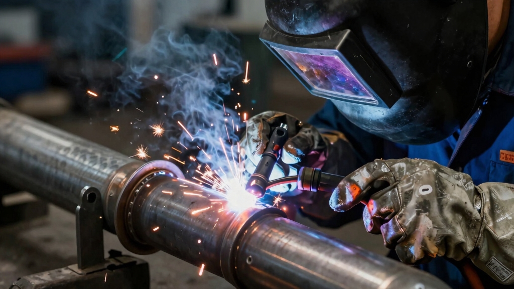
To MIG weld exhaust tubing, first clean and secure tight, square joints with clamps and multiple tack welds to prevent movement.
Set your welder with 0.030-inch ER70S-6 wire, 75/25 argon/CO2 gas, and amperage between 63–140 amps based on thickness.
Use short, high-amp bursts and the push technique at a 10–15° angle to ensure full penetration without burn-through.
Alternate sides during welding to control heat and distortion. Mastering these steps ensures strong, clean exhaust welds with minimal defects.
Mastering MIG welding on thin exhaust tubing requires precise control over heat and technique to prevent burn-through while ensuring solid penetration.
Precise heat control and technique are essential to avoid burn-through and achieve strong welds on thin exhaust tubing.
Begin by thoroughly cleaning and aligning your tubing joints, marking them for accuracy. Use tight butt or slip joints with minimal gaps to stabilize the weld pool.
Employ quick tack welds evenly spaced to hold parts securely, allowing cooling between each to avoid overheating. When welding, apply the push technique, driving the wire into the root while stacking a controlled puddle.
Avoid continuous welding runs; instead, weld in short bursts on approximately 1-inch sections, pausing 3-4 seconds to let metal cool. Alternate welding directions to distribute heat evenly.
These steps help you maintain weld integrity without compromising the thin tubing’s delicate structure. Additionally, selecting compatible filler materials such as ER70S-6 wire can enhance arc stability and reduce spatter for cleaner welds.
After securing your tubing with properly spaced tack welds and managing heat to prevent burn-through, focus shifts to selecting the correct MIG welder settings.
Use the welder’s door chart as your guide for voltage, wire feed speed, and amperage, matching these to your tubing thickness. For thin exhaust tubing, aim for 90-140 amps with 0.030-inch ER70S-6 wire.
Adjust voltage between 18-23 volts, increasing amperage for better penetration but avoiding excessive burn-through. Keep your wire feed consistent to maintain a stable arc and clean weld bead.
Ensure you use the recommended DCEP polarity for solid wire MIG welding to optimize penetration and arc stability.
| Thickness (in) | Voltage (V) | Amperage (A) |
|---|---|---|
| 0.020 – 0.030 | 18 – 20 | 90 – 110 |
| 0.030 – 0.040 | 20 – 22 | 110 – 130 |
| 0.040 – 0.050 | 22 – 23 | 130 – 140 |
| 0.050+ | 23 | 140 |
Select a wire and gas mix designed specifically for thin exhaust tubing to achieve clean, strong welds with proper penetration. Use 0.030-inch ER70S-6 wire, which offers excellent control and consistent deposition on thin walls.
Pair it with a 75/25 argon/CO2 gas mix to stabilize the arc, reduce spatter, and improve bead quality. This combination guarantees efficient fusion and minimizes burn-through risks.
Avoid flux-cored wires unless specified for your application, as they can produce excessive heat and splatter. Adjust your wire feed speed and amperage based on the tubing thickness, referencing your welder’s settings chart for precision.
Proper wire and gas selection is critical to maintain the exhaust tubing’s integrity while delivering welds that withstand heat and vibration over time. Using the recommended gas blend helps balance penetration and spatter control for optimal weld quality.
Choosing the right wire and gas mix sets the foundation for strong welds.
Properly preparing and securing exhaust tubing joints guarantees consistent alignment and penetration during welding.
Begin by thoroughly cleaning tubing ends. Remove rust, oil, and debris for optimal fusion.
Mark joint positions with a Sharpie to maintain precise alignment throughout the process.
Verify a tight fit with minimal gap at butt or slip joints. Excessive gaps increase burn-through risk and reduce weld quality.
Use clamps or locking pliers to hold tubing firmly in place, preventing movement during welding.
Confirm that tubing edges are square and properly beveled if needed.
Double-check alignment before welding to avoid rework.
Proper joint preparation reduces weld defects, improves penetration, and guarantees a durable exhaust system.
Controlling heat input during welding is essential to minimize distortion and prevent weld defects in exhaust tubing.
When you’re welding, it’s really important to control the heat, especially with thin metal. So, try using short bursts of welding. This way, you can apply heat exactly where you need it without overheating the material.
Take a moment between each tack weld to let the metal cool down. This little pause can make a big difference in preventing burn-through.
Also, don’t forget to place multiple tack points evenly around the joint. This will help stabilize the tubing before you dive into completing those full seams. It’s all about keeping things steady and controlled!
Maintaining a steady torch angle of 10° to 15° from vertical during welding helps improve arc stability and reduce spatter.
Frequently, short burst welding proves essential when working with thin exhaust tubing to prevent burn-through. You’ll use quick, controlled bursts of welding current, allowing the metal to absorb heat without melting through.
This technique requires precise timing and amperage control, typically running at higher amps for short durations. Tack weld multiple points evenly to stabilize the joint before completing seams. Avoid continuous welding; instead, weld 1-inch sections and pause briefly to maintain control over heat input.
Maintaining a short arc length during these bursts helps stabilize heat input and prevents excessive puddle fluidity.
| Burst Length | Amperage Range | Pause Duration | Purpose | Result |
|---|---|---|---|---|
| 1–2 seconds | 90–140 amps | 3–4 seconds | Controlled heat | Prevents burn-through |
| 0.5 seconds | 100–130 amps | 2–3 seconds | Deep penetration | Strong weld root |
| 1 second | 110–140 amps | 3 seconds | Tack welding points | Stabilizes joint |
| 1.5 seconds | 90–120 amps | 4 seconds | Fill small gaps | Uniform weld bead |
| 2 seconds | 120 amps | 3 seconds | Final pass | Clean, low-profile weld |
Inserting cooling pauses between weld passes is critical to prevent burn-through when working with thin exhaust tubing.
After each short tack weld, stop welding and allow the metal to cool for 3 to 4 seconds.
This brief pause reduces heat buildup, stabilizes the joint, and prevents warping or melting through the tubing.
Use quick, high-amp bursts for penetration but never weld continuously.
Instead, alternate sides or sections to distribute heat evenly.
During these pauses, monitor the tubing temperature by touch or visual cues.
If it feels too hot, extend the cooling time.
Maintaining tight gaps and clean surfaces also helps control heat flow.
Employing work–rest cycles based on heat input can further minimize heat stress and material damage during welding.
Consistently applying multiple tack welds at evenly spaced points stabilizes thin exhaust tubing and prevents burn-through during full seam welding.
Begin by aligning the tubing with minimal gaps. Quickly apply tack welds at 1- to 2-inch intervals using high amperage bursts.
Allow each tack to cool before moving to the next to avoid excessive heat buildup. This approach secures the joint and distributes heat evenly, reducing distortion.
Alternate sides or directions when tacking to balance thermal input. Multiple tack points hold the metal firmly, preventing movement that could cause burn-through when you complete the seam weld.
Remember to keep the tacks short and controlled, avoiding continuous welds until the entire seam is tacked. This strategy guarantees a stable, clean weld on thin exhaust tubing.
Welding techniques like these are similarly critical when performing a welded differential, where precise and secure locking of components is essential for functionality.
Mastering heat and amperage control is critical when MIG welding thin metal to prevent burn-through and guarantee strong, clean welds.
Set your welder amperage between 63 and 90 amps for thin exhaust tubing, using 0.030-inch ER70S-6 wire and a 75/25 argon/CO2 gas mix.
Adjust wire feed speed carefully to regulate heat input. Too fast increases amperage and risk of burn-through; too slow causes weak penetration.
Reference your machine’s door chart for exact settings based on steel thickness.
Maintain high amperage settings with short bursts to achieve deep penetration without overheating.
Keep your torch angle steady and use the push technique to control puddle size.
Always test on scrap metal to dial in precise heat and amperage before welding actual exhaust tubing.
Using a 75/25 argon/CO2 blend helps improve arc stability and penetration while reducing spatter compared to pure argon.
Controlling heat and amperage sets the stage, but managing cooling during welding truly prevents burn-through on thin exhaust tubing.
To do this, weld in short bursts instead of continuous seams. Trigger the welder for 1-inch sections, then pause 3 to 4 seconds to let the metal cool locally.
This reduces excessive heat buildup that causes burn-through. Alternate welding sides or directions to distribute heat evenly and avoid hotspots.
Use quick, high-amperage bursts to achieve penetration without lingering heat. Avoid long continuous arcs; they overheat and warp the tubing.
Maintaining controlled heat input is essential to minimize distortion and ensure weld integrity when working with thin materials.
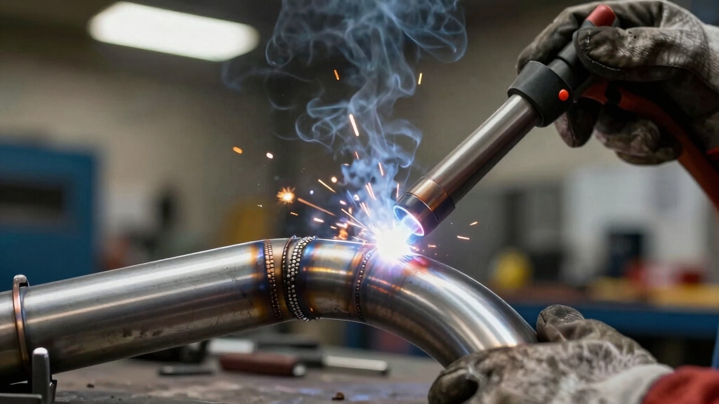
When welding thin exhaust metal, applying the push technique improves bead control and penetration.
Hold the MIG gun at a 10-15 degree angle, pushing the wire and molten puddle forward rather than dragging it back. This directs heat into the joint root, ensuring deeper fusion without excessive burn-through.
Maintain a steady travel speed to stack the weld puddle smoothly and prevent overlap or undercut. Use a 0.030-inch ER70S-6 wire with a 75/25 argon/CO2 gas mix, set amperage between 63-90 amps for thin tubing.
The push technique also reduces spatter and produces a flatter bead profile, ideal for exhaust tubing’s delicate walls. Remember to alternate short weld sections and allow cooling to avoid overheating thin metal while keeping penetration consistent.
After applying the push technique and completing your weld passes with controlled, short bursts, focus on refining the weld beads for strength and appearance.
Assure each bead is low-profile and well-penetrated, confirming full root fusion along the seam. Use a belt sander or flap disc to smooth the weld surface, removing any high spots or unevenness without thinning the metal.
Ensure each weld bead is smooth, low-profile, and fully fused for strength and a clean finish.
Inspect the seam closely for gaps or undercuts. If found, perform additional short spot welds to fill and reinforce these areas. Maintain consistent heat input during finishing to avoid warping or burn-through.
Your goal is a flat, uniform bead that supports durability and allows for seamless coating. Proper finishing not only strengthens the exhaust joint but also guarantees a clean, professional look.
To make certain your MIG welded exhaust sections withstand heat and corrosion, you need to apply proper protective coatings immediately after welding.
First, allow the welds to cool to room temperature to prevent trapping moisture.
Then, thoroughly clean the surface with a wire brush or sandpaper to remove slag, oxidation, and oils.
Apply a high-temperature primer designed for exhaust components to enhance paint adhesion and corrosion resistance.
Once the primer dries, apply a high-temp spray paint rated for temperatures up to 1200°F (650°C).
Use even, light coats to avoid runs and guarantee full coverage.
Let each coat cure as per manufacturer instructions before applying the next.
This protective layer will preserve weld integrity and extend your exhaust’s service life under extreme heat conditions.
You need a welding helmet with an appropriate shade to protect your eyes from intense UV and infrared light.
Wear flame-resistant gloves and a long-sleeve jacket to shield your skin from sparks and heat.
Use safety glasses under the helmet for extra eye protection.
Respiratory protection is essential; use a respirator or work in a ventilated area to avoid inhaling fumes.
Don’t forget hearing protection if noise levels are high.
To troubleshoot MIG welding defects on exhaust pipes, first check your wire feed speed and voltage. They must match the steel thickness.
Clean the tubing thoroughly to avoid porosity. If you see burn-through, reduce amperage or tack weld in short bursts.
Fix lack of fusion by increasing heat or adjusting angle to stack the puddle properly.
Address spatter by adjusting gas flow or wire speed, and always use tight joints to prevent gaps.
Think of welding without ventilation like swimming in a pool full of invisible toxins.
You shouldn’t MIG weld exhaust tubing without specialized ventilation because fumes contain harmful gases and particulates from metal and coatings.
Use a dedicated exhaust fan or fume extractor to pull fumes away, and weld in a well-ventilated area.
Wearing a respirator designed for welding fumes adds essential protection.
Always prioritize safety to avoid respiratory hazards.
You’ll want to clean the nozzle and contact tip after each project to prevent spatter buildup.
Check and replace worn tips regularly for consistent arc quality.
Inspect and clean the drive rollers and liner to avoid wire feed issues.
Make certain gas flow is steady and hoses aren’t cracked.
Finally, wipe down the welder exterior and store it in a dry place to protect internal electronics and cables from damage.
Temperature changes cause exhaust tubing to expand and contract, which can stress your welds and lead to cracks or leaks over time.
While heat improves weld penetration initially, repeated cycles create fatigue that weakens the metal.
You’ll want to use precise welding techniques and allow cooling pauses to minimize thermal shock.
Proper material selection and controlled heat input reduce deformation, ensuring your welded exhaust performs reliably despite constant temperature fluctuations.
You might think welding thin exhaust tubing is fragile work, but with precise settings, careful tack welds, and short bursts, you turn vulnerability into strength.
Applying the push technique and finishing seams smoothly transforms delicate metal into a durable system. Just as the exhaust withstands heat and pressure, your skill protects every joint.
Master these steps, and what seems like a challenge becomes a reliable, long-lasting weld that performs under the toughest conditions.